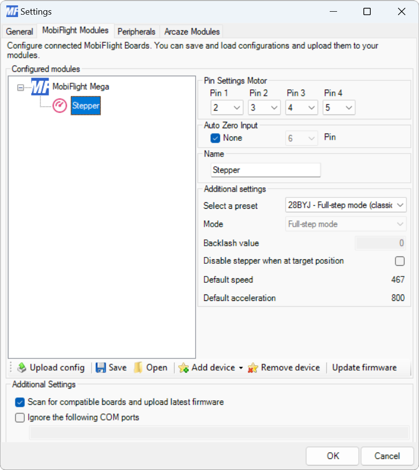
| Pin 1 |
The board pin connected to pin 1 on the stepper motor. All digital and analog pins are supported. |
| Pin 2 |
The board pin connected to pin 2 on the stepper motor. All digital and analog pins are supported. |
| Pin 3 |
The board pin connected to pin 3 on the stepper motor. All digital and analog pins are supported. This pin is not used with Easy Driver boards. |
| Pin 4 |
The board pin connected to pin 4 on the stepper motor. All digital and analog pins are supported. This pin is not used with Easy Driver boards. |
| Auto Zero Input - None |
When checked, disables automatically setting the motor zero position based on a pin input. |
| Auto Zero Input - Pin |
The board pin connected to a switch that, when closed, indicates the motor is at the zero position. |
| Name |
The name for the stepper motor. Displayed in the output configuration dialog to identify the device when mapping the simulator output. |
| Select a preset |
The preset for the type of driver connected to the motor. |
| Mode |
The type of driver mode used. |
| Backlash value |
The number of steps to apply to compensate for backlash in the stepper motor. |
| Disable stepper when at target position |
When checked, turns off power to the stepper motor once it reaches the target position. |